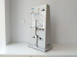
4. Fisher Sub Sieve Sizer Structure
Fisher Sub Sieve Sizer Structure
1. Water Level Observation Window: observe water level in constant pressure regulator
2. Size Pointer: show particle size on calculator chart
3. Powder Porosity (Percentage of Voids) Pointer: show percentage of voids on calculator chart
4. Rack and Pinion Control: anticlockwise turn to move pinion downward and enter sample tube to press the powder until reaching required height, size pointer show value on the calculator chart. When turn it clockwise, the pinion move upwards and leave the sample tube.
5. Pinion
6. Clamp Assembly Control: when the sample tube or AimSizer sub sieve sizer calibrator was placed on the test base, turn clockwise to press and seal the top and bottom of the sample tube or sub sieve sizer calibrator.
7. Bubble Observation Window: observe the bubble status
8. Pressure Control: turn to change the exhaust volume of pressure valve to make the inlet pressure of sample tube P=50 cm water column pressure, when adjusting, observe and make the exhausted bubble number from the constant pressure regulator 2 to 3 per second, keep such rate during the test.
9. Base Block Assembly
10. Test Base
11. Manometer Level Control: turn it to make the manometer water level on zero position. Clockwise turn to increase the water level, anticlockwise to reduce.
12. Power Switch
13. High Needle Valve: when calibrating the HMK-22 using sub sieve sizer calibrator, turn the knob to make the pointer stop at the High Value marked on the sub sieve sizer calibrator. Turn clockwise to increase the value and anticlockwise to reduce.
14. Low Needle Valve: when testing samples in 20 to 50 um, switch the range control to II, now the high value is set and not possible to reset, turn the knob to make the pointer stop at the Low Value marked on the sub sieve sizer calibrator, clockwise to increase the value and anticlockwise to reduce the value.
15. Manometer Level pointer: the line tangent the bottom of the crescent water level and the size pointer shows the fisher number on the calculator chart.
16. Calculator Chart: HMK-22 Fisher Sub Sieve Sizer show the size, sample height and powder porosity (percentage of void)
17. Range Control: when measuring powder in 0.2 to 20 um, switch left, i.e. I. For powders 20-50 um switch to right that is II.
18. Outside Manometer
19. Back
20. Rubber Plug
21. Sample Pressure Calibrator
A – Water Level Observation Window H – Clamp Assembly Control
B – Range Control I – Manometer Level Control
C – Calculator Chart J – Base Block Assembly
D – Outside Manometer K – Sample Tube
E – Rack and Pinion Control L – Power Switch
G – Pressure Control N – Metal Marker Bar
Fisher sub sieve sizer https://www.aimsizer.com

